Camera input
AI AGENT ROVER / THE PROJECT
Giving an AI Agent
access to the world.
Can Grok Bot do more than talk about the world? Can it act in it? This rover is an experiment in what an AI can see, understand and control, and where it reaches its limits.
FROM SIMULATION TO PHYSICAL CONTROLAIAgentRover.com
MEET THE MACHINE / V8SPIN ME
Loading the rover…
Drag to rotate · Scroll to zoom · Double-click to reset
01 / PROJECT QUESTIONS
The six project questions
One rolling experiment, with a new capability to test at each step. The aim was to understand what Grok Bot could do in the physical world and where it reached its limits.
Servo control
Can it control a basic output?
Simulation
Can it navigate a simulated world?
Steering and movement
Can it steer and move the real car?
System integration
Can it use all the components together?
Untethered operation
Can it operate without bench power?
02 / DEVELOPMENT
Development approach
Increase the complexity in stages. Prove individual parts, combine them, then check whether the same behaviour holds up on a moving rover.
Prove the basics
Begin with the camera, then an unloaded servo. Check that Grok Bot can interpret an observation, issue a simple command and recognise the resulting change.
Test in a simulated world
Give Grok Bot a virtual rover and a house to explore. Test navigation, mapping and the search for a moving dog before introducing physical driving.
Build and test each component
Check the camera, servo board, range sensor, steering and ESC separately. Then assemble the rover and retest the complete system, including cable clearance, calibration and stop behaviour.
Test untethered
Replace bench power with the Pi power bank and the car battery. Run supervised tests with the mounted hardware, checking supply stability, movement and reliable stopping.
COMPONENT TEST NOTES
Component tests and findings
Select a component to see why it was tested separately.
TEST 01 / CAMERA ONLY
Camera input
Start the Pi helper with drive and servo output disabled. Check a fresh camera picture and real IMX500 detections before adding motion.
Lesson: A live image, a detection result and a timely observation are different things. Camera and network delay matter once the car starts moving.
View the hardware test interface
Camera, steering, drive and range checks were brought together in a single development interface.
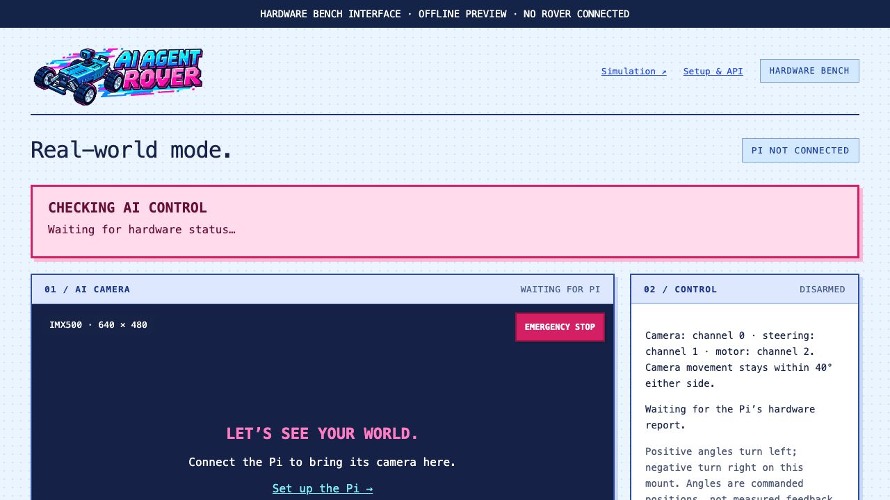
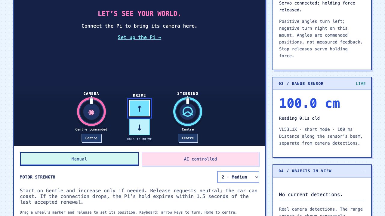
The hardware controls are private. These screenshots are for illustration and do not operate the rover.
03 / SIMULATION
Testing in a simulated world
A controlled environment for testing whether Grok Bot could turn observations and individual commands into useful navigation.
TEST OBJECTIVE
Test navigation before physical driving
Before asking Grok Bot to drive the real rover, the project gives it a virtual one. The bot can request a camera image, inspect detections, choose a short movement and observe the result without putting a physical car, furniture or pets in the experiment.
The challenge is more than spotting a dog. Can Grok Bot work out where it is, choose a route, cope when the dog moves and recover when an action does not do what it expected?
01 Observe the camera02 Choose the next move03 Act through the API04 Check what changed
PROJECT OUTCOME
Grok Bot mapped the house and found the dog
In the simulated environment, Grok Bot was able to map the house and locate the simulated dog. This demonstrated that it could combine observations, spatial reasoning and movement commands to complete the task.
The next question was whether those capabilities would transfer to real hardware, with camera delays, power constraints and imperfect movement.
TRY THE SIMULATION
Can you outperform Grok Bot?
Take the wheel and try the same type of navigation challenge. This visitor version runs locally in your browser and does not connect to Grok Bot or the real rover.
The three-minute limit is a visitor challenge, not Grok Bot’s recorded completion time. No matched timing comparison is available.
YOUR MISSION
You have three minutes to find the dog as it wanders through the house. Drive close enough to see it, then release the controls and stay still for two seconds before the countdown reaches zero. Pausing also pauses the clock.
MISSION 01 FIND THE DOG
TIME LEFT 03:00LIVING0 FOUND
Explore the house
WASD or arrow keys · SPACE pause
The visitor game is inspired by the Grok Bot testing environment, with a wider dog route for exploration. The floor plan, movement and object visibility are simplified; the real-world missions described below tested those capabilities on the physical rover.
What does the Grok Bot test environment let us evaluate?
Perception & decisions
Does the bot use fresh observations, distinguish the target from other objects and choose a useful next action?
Navigation & recovery
Can it move between rooms, search for a moving dog and recover after a blocked or unhelpful movement?
Control & restraint
Does it use bounded commands, check the result before retrying and respect human takeover?
The mapping and dog-finding result is a project observation, not a controlled benchmark. The simulation’s object labels are synthetic ground truth; they do not validate the real camera’s detection accuracy. Real power, traction, braking and connection delays require separate physical tests.
04 / PHYSICAL TESTING
Real-world results
Component testing
Separate tests brought up the camera, camera pan and steering controls. The ESC responded to forward and braking commands, and the range sensor produced plausible standalone measurements after its protective film was removed.
Two missions completed
Grok Bot was given two real-world missions: map the house and find the dog. It successfully completed both.
These runs showed that Grok Bot could understand its real-world surroundings and control the rover with only a high-level mission outline.
Project video
Watch the rover adventure with commentary from the project.
Development challenges
Power-bank dropouts
Power trouble was reported with the bank still showing 65%, and later 88%. Neither observation established a charge-level cutoff. The bank, cable, PD negotiation and connections needed checking as a complete chain.
Failures after mounting
Mounting the power board above the Pi introduced a new clue. The next isolation test was to unmount it and compare the same power path, checking underside contact, spacers, button pressure and USB-C seating. A cause was not yet confirmed.
Control signals and motor power
Stronger settings change the ESC control pulse. They cannot repair a weak supply or a loose connection. The thick battery-to-ESC-to-motor path carries the current; the PCA sends the instructions.
05 / HARDWARE AND BUILD
Building Grok Bot
The component layout, power arrangement and parts needed to build a similar rover.
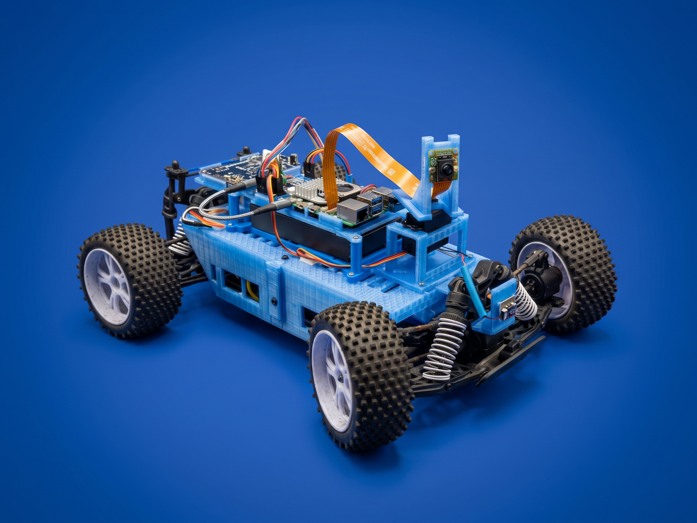
How the components work together
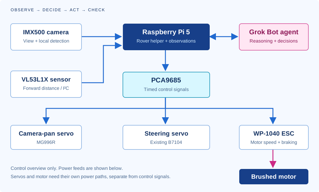
Raspberry Pi 5
On-board computing
Runs the rover helper, handles camera observations and passes commands to the control hardware. The current software does not need the separate AI HAT.
IMX500 AI camera
On-camera detection
The camera runs the object-detection model. A pan servo lets it look left and right. Grok Bot can reason about observations, but the camera’s detection is local.
PCA9685 board
Camera, steering and ESC signals
Channel 0 pans the camera. Channel 1 steers. Channel 2 sends commands to the ESC. It generates timed pulses; it does not supply the drive motor’s high current.
52Pi PD board
USB-C power conversion
The RPi5 PD Power board sits between the USB-C power bank and the Pi. It handles power conversion and provides the PowerON button and Always-ON setting.
5 V UBEC
A separate regulated supply
A branch from the car battery feeds the DC/DC converter. Its regulated output supplies the PCA’s V+ servo rail. The discussed 3 A rating is a total budget, not 3 A for each servo.
WP-1040 ESC
Brushed motor control
The electronic speed controller takes power from the 7.2 V car battery and controls the brushed motor. The Pi and PCA take over the radio receiver’s command role; the ESC stays.
VL53L1X sensor
Forward distance readings
A forward-facing distance sensor adds another observation. Testing uncovered protective film and a settings mismatch. A missing reading means distance unknown.
Grok Bot + the API
Agent observation and control
Grok Bot uses authenticated tools to observe and request actions. Simulation access and real hardware access are separate, and a human chooses when AI control is allowed.
THE CONTROL LINE-UPCH 0 Camera panCH 1 SteeringCH 2 ESC command
Power sources and distribution
The Pi has its own USB-C power bank. The car battery supplies the ESC and a regulated branch for both servos. Select a path to see how power reaches each part.
SOURCE A
USB-C PDPower bank
→CONVERT & SWITCH52Pi PD board
→COMPUTE & VISIONRaspberry Pi 5
SOURCE B
7.2 VCar battery
→HIGH-CURRENT CONTROLWP-1040 ESC
→THE DRIVETRAINBrushed motor
B / BRANCH
FROM CAR BATTERYBattery takeoff
→REGULATE TO 5 VUBEC converter
→PCA V+ RAILCamera + steering
A / KEEP THE BRAIN AWAKE
Bank → board → Pi.
The power bank connects to the PD board’s INPUT. A second USB-C cable connects OUTPUT to the Pi. A blue light on the board alone does not confirm that the Pi is receiving usable power.
Functional overview of the selected arrangement, not a pin-by-pin wiring diagram. Logic and servo power are different rails with a common ground. The ESC’s red BEC output stays isolated from the separate UBEC-powered rail. Combined servo load still needs checking.
The electrical details that made a difference
The PD board documentation describes a default 15 V USB-PD input and a regulated output for the Pi. Its INPUT and OUTPUT have distinct jobs. PowerON and Always-ON also affect startup; an illuminated board is not the same thing as a booted Pi. 52Pi board documentation.
On the PCA board, VCC is the 3.3 V logic supply; V+ is the separate servo supply. Shared ground gives control signals a common reference. It does not mean connecting positive supplies together. Adafruit power and wiring guide.
The battery takeoff also means the ESC switch does not necessarily turn off the UBEC branch. The real build’s power-off procedure has to account for both batteries and every branch.
Full parts list
Retain the existing RC components where suitable, then add the computer, sensors and control hardware. Camera pan and steering use separate servos.
38 line items · 6 categories · 2 very different servos
Download shopping listThis is a reference for a similar build, not a guaranteed plug-and-play kit. Quantities are starting points. Match connectors, dimensions, ratings and the actual hardware before buying.
MG996R
An added positional servo that rotates the camera. Match the holder, horn and travel to the unit you actually buy.
B7104 “3kg”
The retained RC steering servo, as recorded in the close-up discussion. Verify its label and specifications; the torque marking does not tell us current draw.
0 of 38 items checked · Tick items you already own or have sourced. Checks last for this page visit.
RC platform 6 items
| Got it | Part | Qty | What to check |
|---|---|---|---|
| RC car chassis and drivetrainRetain | 1 | Use the existing rolling chassis, suspension, wheels and body fixings. A different car needs fresh measurements. | |
| Brushed drive motorRetain | 1 | Keep the motor matched to the ESC and battery. Do not buy a brushless replacement for a brushed ESC. | |
| WP-1040 brushed ESCRetain | 1 | Existing controller; verify its exact label, battery compatibility, startup and reverse behaviour. | |
| Steering servo - B7104, marked “3kg”Retain / verify | 1 | Existing car servo, recorded as B7104 in the close-up discussion. Verify the actual label, voltage, spline and linkage; “3kg” is torque shorthand, not current. | |
| 7.2 V car batteryRetain / verify | 1 | Confirm chemistry, capacity, condition, connector and ESC compatibility on the actual pack. | |
| Battery chargerMatch to pack | 1 | Use the charger and settings for the actual battery chemistry and cell count; not the Pi power-bank charger. |
Compute & vision 6 items
| Got it | Part | Qty | What to check |
|---|---|---|---|
| Raspberry Pi 5Add / reuse | 1 | RAM capacity was not confirmed in the project record. Choose after checking your intended workload. Reference / source | |
| Pi 5 cooling assemblyAdd / reuse | 1 | The build retains active cooling. Leave airflow and clearance beneath stacked boards. Reference / source | |
| microSD card or supported boot storageAdd / reuse | 1 | For Raspberry Pi OS and the rover helper; capacity/model to suit your installation. | |
| Raspberry Pi AI Camera - IMX500Add | 1 | Runs object detection on the camera. The separate AI HAT is not required by this project’s current software. Reference / source | |
| Pi 5-compatible camera ribbon cableCheck included | 1 | Match both connectors and allow the camera to pan without pulling or sharply folding the ribbon. Reference / source | |
| VL53L1X distance-sensor breakoutAdd | 1 | Confirm the exact breakout and logic compatibility. The linked board is a sourcing example, not a claim about the installed brand. Reference / source |
Control & power 8 items
| Got it | Part | Qty | What to check |
|---|---|---|---|
| Camera-pan servo - MG996RAdd | 1 | Positional servo matched to the camera holder. Check actual dimensions, horn spline, travel and current; do not substitute a continuous-rotation version. Reference / source | |
| Matching servo horn and retaining screwCheck included | 1 set | Must fit the actual MG996R shaft and camera adapter. It may be included with the servo. | |
| PCA9685 servo/PWM driver boardAdd | 1 | Camera CH0, steering CH1, ESC command CH2. Check board quality, headers and power rails. Linked Adafruit board is a sourcing example. Reference / source | |
| 52Pi RPi5 PD Power board - EP-0225Add | 1 | The power board used in the project. Match the bank’s USB-PD profile and distinguish INPUT from OUTPUT. Reference / source | |
| USB-C PD power bankSelect & validate | 1 | Exact bank model not confirmed. Verify the PD profile needed by the board, sustained load, cable fit and mounted dimensions; battery percentage alone is not enough. | |
| USB-C to USB-C power cablesCheck included | 2 | Bank → board INPUT and board OUTPUT → Pi. Match power ratings and plug clearance; a suitable board-to-Pi cable may already be included. | |
| UBEC DC/DC converter - 5 V, 3 AAdd / validate load | 1 | Project converter: Adafruit 1385 / P1385A as discussed. The 3 A budget is shared by servos; combined peak demand still needs checking. Reference / source | |
| Known-working Pi mains supplyBench tool | 1 | Useful as a reference supply when isolating portable-power problems. Match the Pi 5 requirements. Reference / source |
Wiring & connectors 6 items
| Got it | Part | Qty | What to check |
|---|---|---|---|
| Battery splitter / power takeoff harnessMatch & rate | 1 | Branch the car battery to ESC and UBEC. Match actual connectors and polarity; the project used a Deans/T-style connection with an adapter. | |
| Servo extension leadsMeasure route | 2 as needed | For camera and steering. Check plug orientation, wire rating, movement and access before choosing lengths. | |
| ESC signal/ground adapter leadConfigure correctly | 1 | With a separate UBEC powering PCA V+, isolate the ESC red BEC output. Signal and ground retain their distinct roles. | |
| I²C/GPIO jumper wires or secured harnessMatch headers | 1 set | Pi to PCA and sensor: power, ground, SDA and SCL. Use suitable retention; the motor current never goes through these jumpers. | |
| Insulation and strain-relief suppliesWorkshop supplies | 1 set | Heat-shrink, insulated connectors, cable ties and tie mounts. Keep exposed contacts away from boards and moving parts. | |
| Accessible power isolationDesign for both sources | 1 arrangement | Account for the Pi bank, ESC and servo branch. The ESC switch alone does not cut every branch. |
Prints & fixings 8 items
| Got it | Part | Qty | What to check |
|---|---|---|---|
| V8 front and rear shellsPrint | 1 each | Two parts in the V8 download. Use supplied notes, inspect the slice and physically fit-check. Print files | |
| V8 battery frame with five risersPrint | 1 | Supports the bank and electronics; included in V8 download. Check battery removal and strap clearance. Print files | |
| V8 electronics platePrint | 1 | Included in V8 download. Check real board fixings, insulation and cable-plug access. Print files | |
| Camera cradle, servo holder and horn adapterReuse / adapt | 1 each | Separate fitted components, not included in the four-part V8 package. Match your camera, servo and horn. | |
| Forward range-sensor mountPrint / fabricate | 1 | Keep the sensor fixed facing ahead, with the optical face unobstructed. | |
| Camera screws and nuts - M2 × 6 mmVerify cradle | 4 each | Specified for the camera cradle prototype. Confirm screw engagement and clearance on the actual printed assembly. | |
| Shell screws, washers and board standoffsMeasure stack | 1 assortment | V8 notes specify HP0554 No.4 × 12 mm for shell features. Do not use them in small PCB holes. Select washers and standoffs for actual clearance. | |
| Battery retaining straps and padsFit to assembly | As needed | Secure both packs without pressing a power button or blocking cooling, connectors or removal. |
Tools & software 4 items
| Got it | Part | Qty | What to check |
|---|---|---|---|
| 3D printer or print-service access + filamentWorkshop resource | 1 access | P1S was used as the design target; choose material and supports for the part. Files are unsliced. | |
| Digital multimeter, calipers and hand toolsWorkshop resource | 1 set | Measure voltage, continuity, mounting dimensions and fastener fit. Include suitable drivers and wire/connector tools. | |
| Raised-wheel test supportWorkshop resource | 1 | A stable support that keeps all driven wheels clear while testing steering and ESC behaviour. | |
| Computer, Wi-Fi and software accessRequired | 1 setup | Pi OS, camera libraries, rover helper, protected interface and an AI agent able to call tools. Hosting and AI usage may have separate costs. |
Product links are manufacturer references or clearly labelled sourcing examples, checked 6 October 2026. Availability and prices vary. The exact bank, battery and some mounting hardware still require identification. A separate AI HAT is not on the shopping list because the current detection model runs on the IMX500 camera.
Printed structure and model files
The printed assembly holds the electronics and battery above the RC chassis. Check physical fit, insulation and clearance as you build.
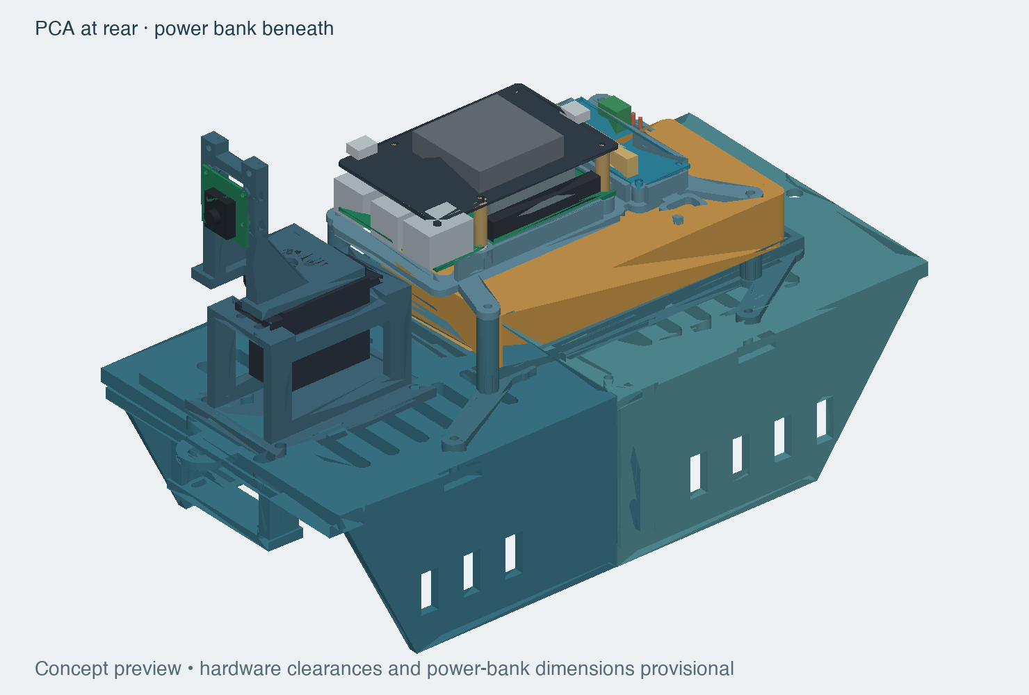 FROM THE WORKBENCH / EARLIER STACKED ASSEMBLYDownload the V8 print models
Four unsliced models, STL alternatives and print notes. The V8 revision still needs physical fit and load checks.
Plan a similar project
Grab the starter prompt, fill in your hardware and goals, and give it to your AI assistant. It walks through the same six questions, from camera input to untethered operation, with component checks and an honest test log at every stage.
A planning starting point, not a ready-to-run wiring guide. It asks the assistant to verify your parts before proposing connections or powered tests.
SAFE TESTING
Safety and human control
Access is deliberate. Commands are limited. A person keeps the final say. The public game never grants access to the physical rover.
Generated access token
A generated access token is part of the setup that lets Grok Bot use the project’s control tools. The owner creates and supplies it deliberately; visiting this website gives no access to the rover.
- Generate a dedicated token. The owner creates an access token within the private control setup for the intended environment. Simulation and physical hardware use separate credentials.
- Pass it securely to Grok Bot. Store the token in the tool configuration’s secret field so authenticated requests can use it. Keep it out of prompts, public pages, screenshots and URLs.
- Allow control explicitly. A token authenticates requests. Human approval, bounded actions and the ability to stop or take over remain separate requirements.
- Revoke access when needed. Revoke or replace the token when access is no longer required or the token may have been exposed.
This is a rover access credential. It is separate from an xAI API key and from the usage tokens a model consumes. No token values or private control links are published here.
Keep controls private
The public website provides no bot keys or links to private control endpoints. The visitor game cannot send commands to physical hardware.
Bounded commands
The simulation API caps a drive command at two seconds and rejects overlapping commands. Read the current state after an uncertain result before sending another move.
Stopping and manual override
Verify manual override, connection-loss behaviour and the physical stop before a powered test. Start with wheels raised, then use a clear, supervised area.
Safe test areas
Keep real animals out of drive tests. A forward sensor cannot cover every direction or detect every drop. A dog found in the game is a virtual mission, not permission to chase a pet.
What has been validated? What still needs testing?
The design files include mesh, assembly and sampled clearance checks. These do not establish printed strength, real cable fit or safe driving performance. The range sensor produced plausible standalone measurements; confirmation in the integrated rover remains a separate test. The game uses synthetic geometry and simplified motion, not a validated physics or perception model.
GET IN TOUCH
Get in touch
Interested in the project, building your own rover, or exploring what AI agents can do in the physical world? Connect with Marty Hungerford.
Connect on LinkedIn ↗